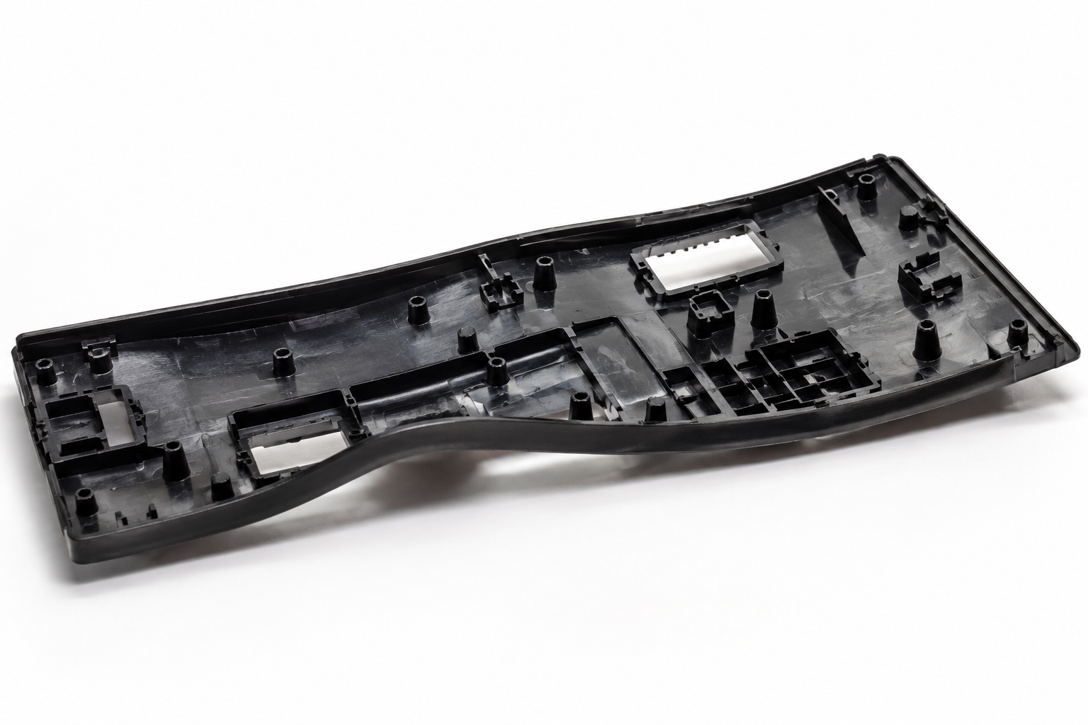
Technical Resource

Processing
troubleshooting guide

A working reference for engineering plastics and polymers. Every common processing defect - what it looks like, why it happens, and the changes that actually fix it - ordered so you can find your fault and act on it in under a minute.

24
Defects documented
3
Processes mapped
200+
Corrective actions
13
Parameters cross-referenced

Most moulding faults are not mysteries. They are a small number of physical mechanisms - shear, trapped air, differential shrinkage, thermal damage and moisture - presenting themselves in different places on the part.

Read the defect description first and confirm you have correctly identified what you are looking at. Several faults look alike but have opposite fixes: a void and a gas bubble sit in different places in the wall; a silver streak from shear and a silver streak from moisture come from different parts of the process. Getting the identification right is most of the work.

Within each fault, remedies are split into process settings you can change at the press this shift, mould & part design changes that need tooling work, and material & machine factors. Always start at the top of the process column - change one variable at a time and give the machine enough shots to stabilise before judging the result.

Start with what you see

Pick the family your defect belongs to, or search all 24 faults.

Fault 01 of 24
01
Surface & appearance

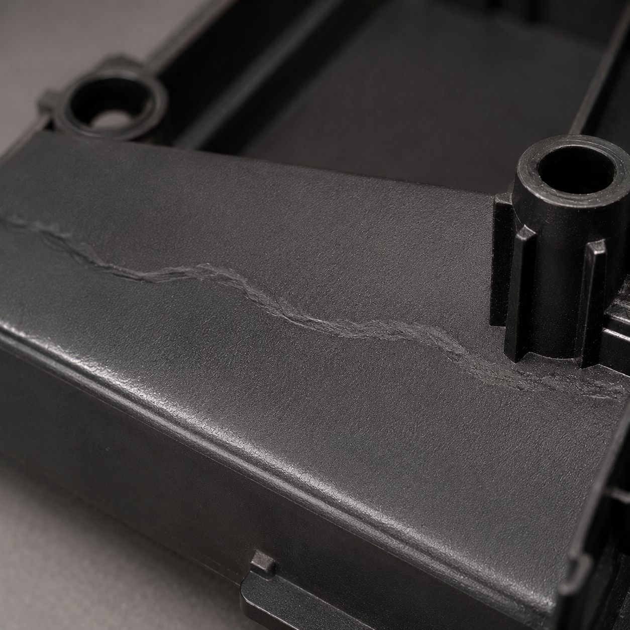
Weld line

Also called: knit line · meld line
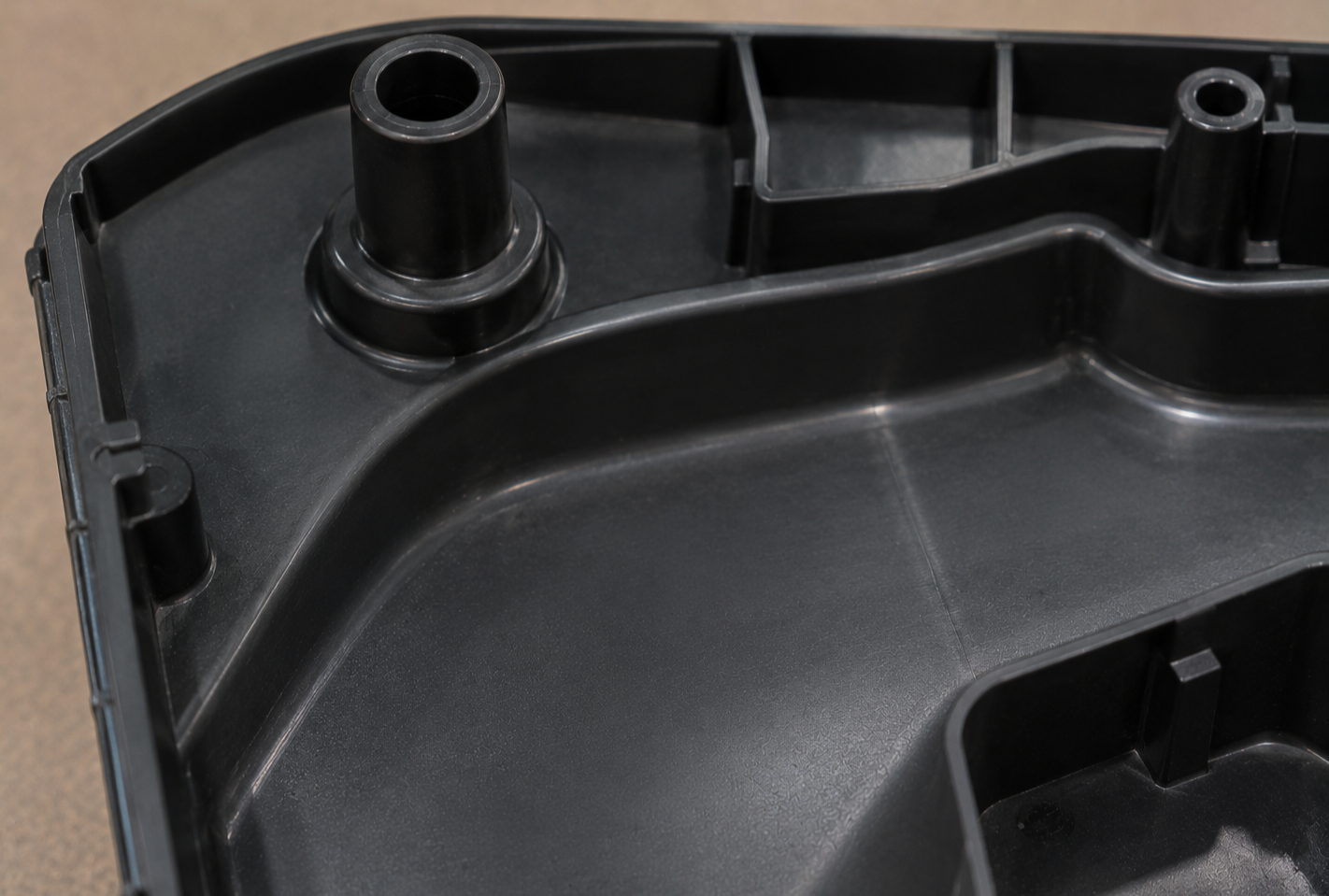
Weld line visible on the surface of a moulded part
Suggested shot Weld line forming downstream of a hole, photographed under vertical illumination so the notch catches the light. A second frame showing glass-fibre orientation across the joint works well alongside it.

What you see

A fine notch - or scratch-like line where two advancing melt fronts have met and fused. It shows up most on dark, transparent or highly polished surfaces, on glass-fibre reinforced grades, and in materials carrying effect pigments. Where the fronts meet too cold and at too low a pressure, the chilled skin no longer presses against the cavity wall and leaves a visible groove. The same cold-front condition also reduces local mechanical strength, because polymer chains and fibres do not bridge the joint.

Why it happens

  • Two or more melt fronts converge - around holes, cores and inserts, or where feeds arrive from opposite sides
  • Differences in flow length, or a change in wall thickness, steer the fronts together in a visible area
  • Temperature and pressure at the meeting point are too low for the fronts to properly re-fuse
  • Air trapped at the convergence point prevents the fronts from pressing together
Process settings
  • Increase melt temperature so the fronts arrive hot enough to re-fuse
  • Switch over to holding pressure just before volumetric fill - around 98 % filled
  • Increase injection speed - but reduce it instead if the weld-line area vents poorly
  • Clean the venting channels
Mould & part design
  • Move the gate, or adjust wall thicknesses, to relocate the weld line to a non-critical area
  • Improve venting in the affected region to help the fronts close
Material & machine
  • A weld line is often unavoidable - run a flow simulation before the mould is cut, when moving it is still free
  • Verify any proposed gate or wall change by simulation before committing to steel
Primary levers Melt temp Injection speed Switchover point Venting Gate position
02
Surface & appearance

Delamination

Also called: layer separation · skin peeling

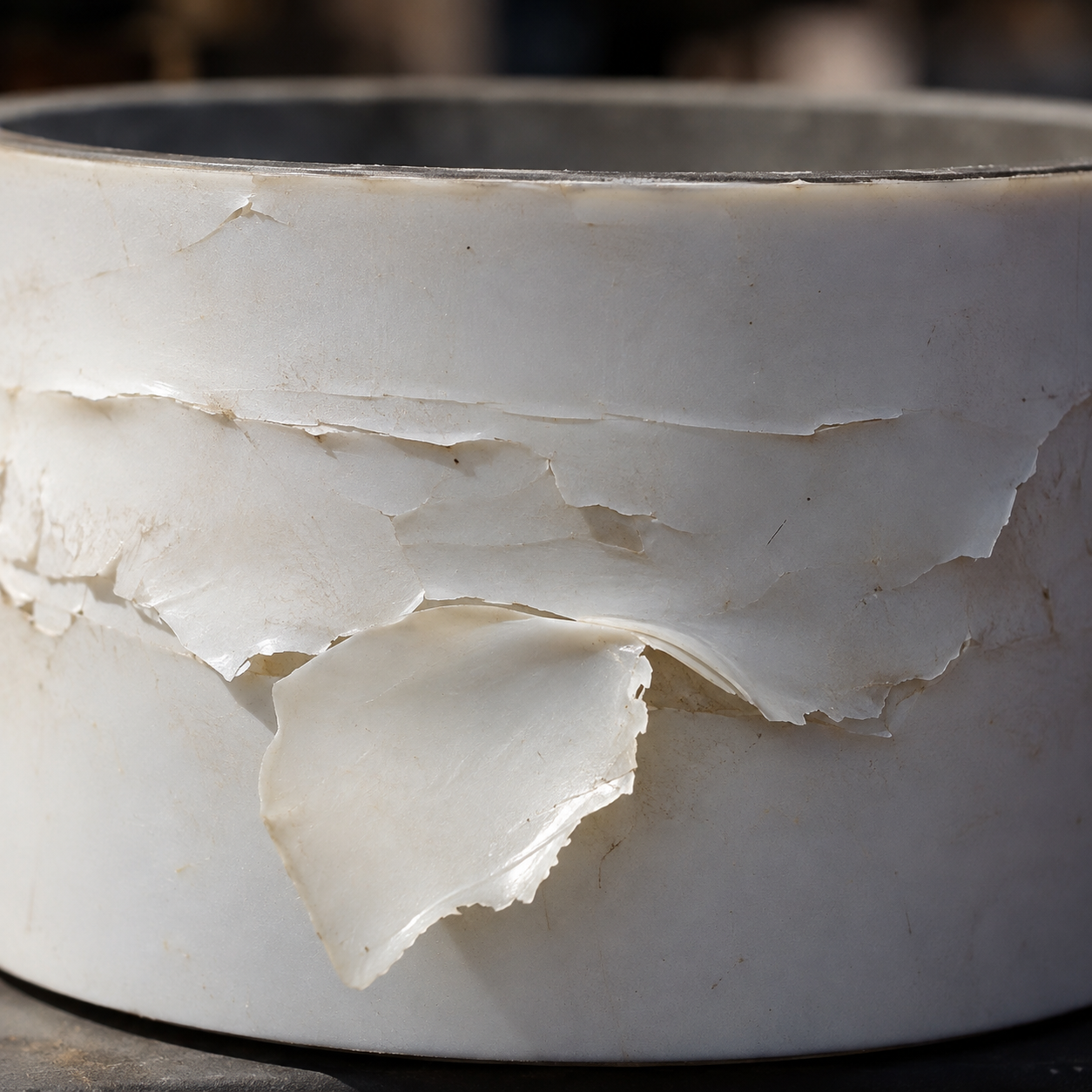
Delamination - surface layers peeling away from a moulded part
Suggested shot A surface skin being lifted away with a blade or fingernail, showing the layered structure underneath. Contamination-driven delamination photographs well as a flaking patch mid-surface.

What you see

Surface layers peel or flake away as thin, detachable skins. The bond between polymer layers has failed, normally because of excessive shear in a relatively cold melt combined with an aggressively cooled mould. In semi-crystalline grades this produces layers with different crystal structures; in amorphous grades it shows as de-mixing of the melt / additive / pigment blend. Contamination with an incompatible polymer produces an identical-looking result, so rule that out first. Most often seen on unreinforced semi-crystalline materials.

Why it happens

  • Excessive shear during cavity filling
  • Machine and possibly the hot runner contaminated with foreign material
  • An incompatible masterbatch - wrong carrier polymer for the base resin
  • Air drawn into the melt during metering
Process settings
  • Increase melt temperature
  • Reduce injection speed to cut shear during filling
  • Raise back pressure while the material is being fed
Mould & part design
  • Enlarge sprue and runner cross sections to reduce pressure loss
  • Change the gate type - a film gate instead of a pin gate lowers shear
  • Increase the wall thickness of the moulded part
Material & machine
  • Purge the machine and hot runner thoroughly before processing
  • Confirm the masterbatch carrier is compatible with the base polymer; change to a suitable carrier if not
  • Check the maximum permissible metering stroke has not been exceeded - move to a larger screw if it has
  • Use an optimised screw design, e.g. a shallow-flighted three-zone screw
Primary levers Melt temp Injection speed Back pressure Runner cross section Masterbatch
03
Filling & venting

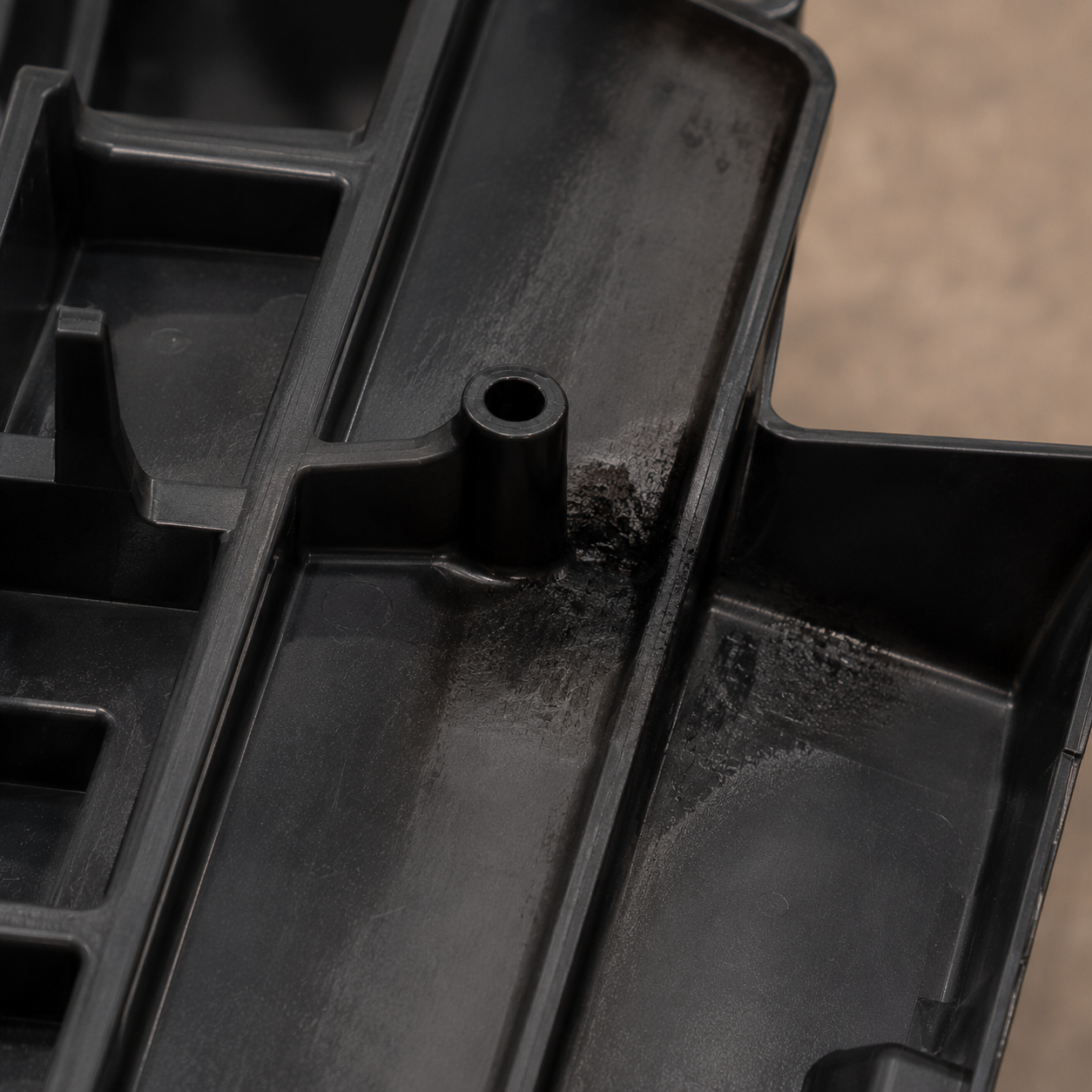
Diesel effect / burning

Also called: dieseling · gas burn · burn marks

Diesel effect - burn marks at the end of the flow path
Suggested shot Charred black tip at the top of a rib, with a companion frame of the same rib after core-pin venting was added - a clean before/after is the most persuasive image for this fault.

What you see

Localised black discolouration at the end of the flow path, at weld lines, or at the top of ribs - often with the part not completely formed at that point. The advancing melt compresses the air ahead of it; if that air cannot escape it is compressed adiabatically and ignites, exactly as in a diesel cylinder, charring the polymer. Look at the tool as well as the part: the same locations frequently show plate-out or corrosion on the mould surface.

Why it happens

  • Injection speed too high - the air has no time to escape
  • Venting channels contaminated or clogged by plate-out
  • Air cannot escape through the parting surface of the mould
  • Mould insufficiently vented in that region
  • Several melt fronts converge and seal off a pocket of air
Process settings
  • Reduce injection speed - often it is enough to slow only the last part of the stroke using a graduated injection profile
  • If burning appears close to the parting surface, reduce clamping force so the parting line can breathe
Mould & part design
  • Clean the venting system and improve the vents
  • Check vent position and effectiveness; add vents in the parting surface and/or fit core pins where melt fronts meet
  • Adjust the flow pattern via gate position or flow leaders so trapped air can reach the parting surface
Material & machine
  • Run a filling analysis to identify exactly which regions fill last - those are where the air ends up
  • Keep vents on a maintenance schedule; plate-out re-blocks them over a production run
Primary levers Injection speed Venting Clamp force Gate position
04
Material & contamination

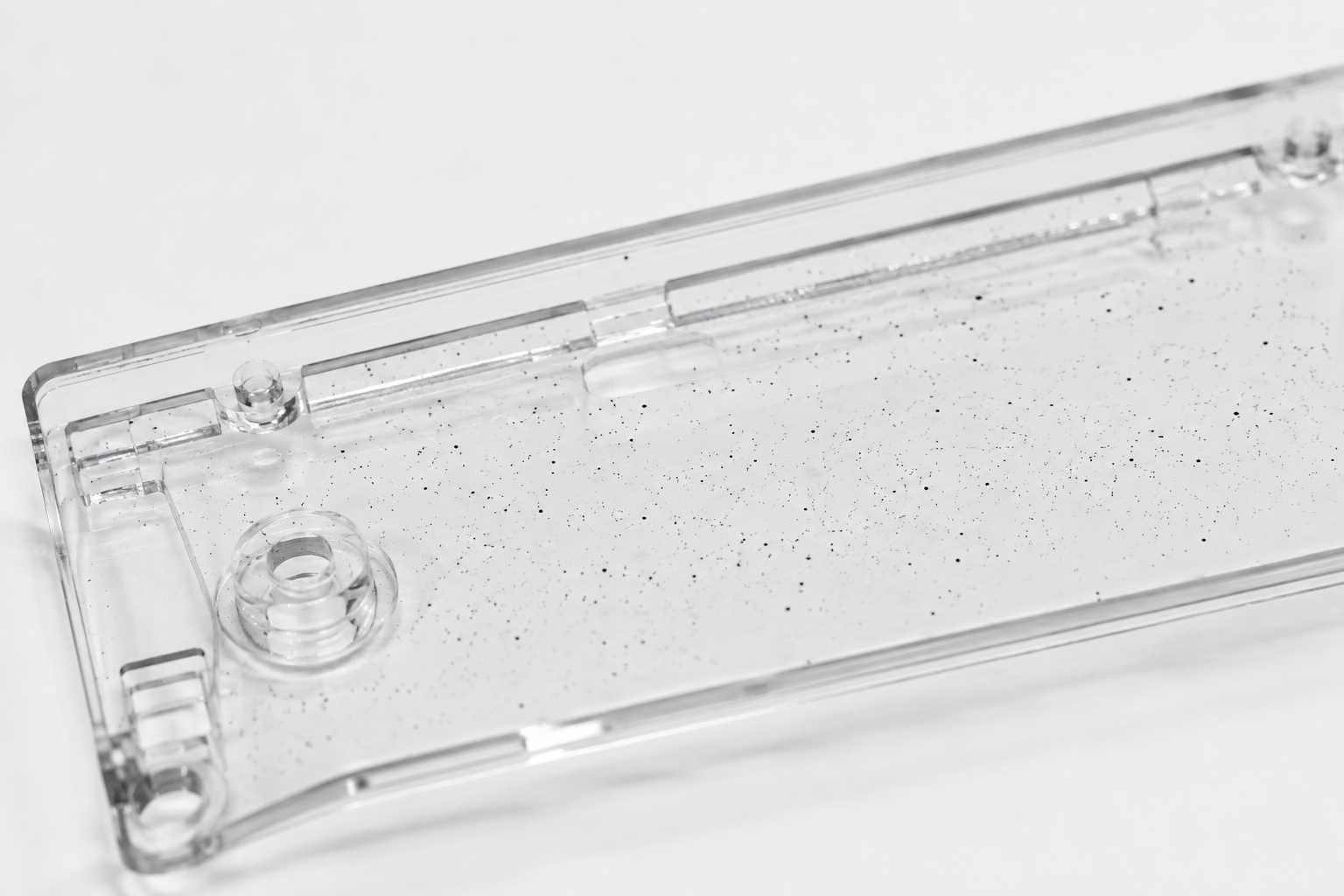
Black specks

Also called: dark inclusions · carbon specks

Black specks contaminating a moulded part
Suggested shot Natural or light-coloured part with scattered dark inclusions, ideally at magnification. A transparent part showing specks suspended through the wall illustrates the difference between surface and through-thickness contamination.

What you see

Dark inclusions on the surface, or - in transparent grades - suspended through the wall. There are two distinct origins and they need different fixes: foreign contamination arriving with the granules or through the conveying system, and the polymer's own thermal degradation products breaking loose from dead spots in the melt path. If specks appear after a standstill or a colour change, suspect the second.

Why it happens

  • Material contaminated with foreign matter
  • Melt temperature too high
  • Material degrading in dead spots in the plasticising unit and/or hot runner
  • Metallic particles breaking loose from a worn plasticising unit or mould
  • Residence time of the melt too long in the barrel and/or hot runner
  • Heating and cooling times too long, or extended machine standstills
Process settings
  • Check melt temperature and lower barrel and hot-runner setpoints if it is running high
  • Reduce screw speed and back pressure
  • Reduce hot-runner residence time - shorter cycle or smaller flow-channel cross sections
  • On high-temperature polymers (PSU / PESU / PPSU), heat up and cool down the barrel in two stages
  • During interruptions, purge frequently and drop the temperature
Mould & part design
  • Eliminate all dead spots - inspect the non-return valve, machine head, nozzle and hot-runner design
  • Check the plasticising unit and mould for wear or partially detached coatings; replace affected components
Material & machine
  • Minimise the time granules are left open to the atmosphere
  • Inspect the conveying system for leaks, deposits and wear
  • Clean the conveying system, dryer and machine thoroughly before any material change
  • Check barrel residence time - change to a smaller barrel or a shallow-flighted screw if it is excessive
Primary levers Melt temp Screw speed Back pressure Residence time Purging
05
Shrinkage & dimensional

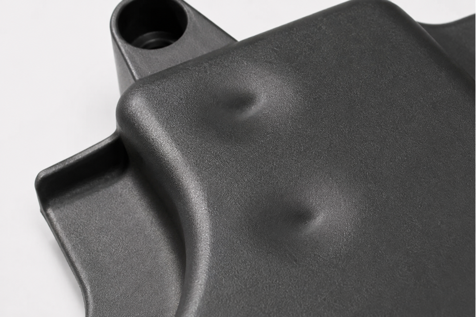
Sink marks

Also called: sinks · shrink marks

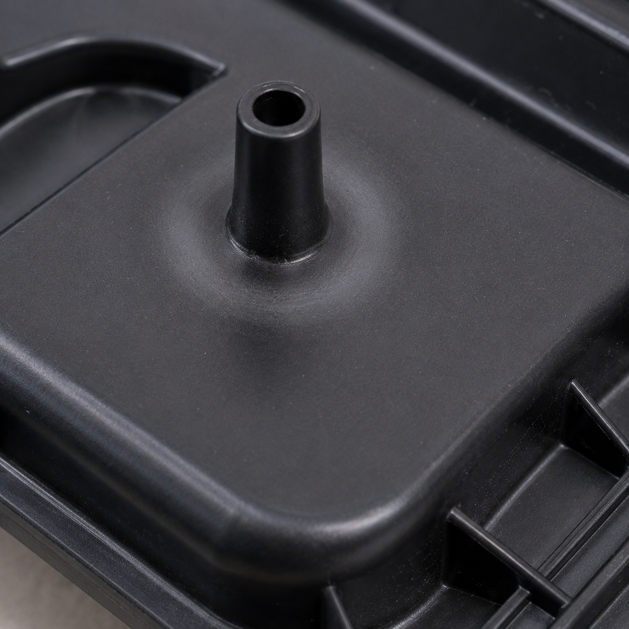
Sink marks on the surface of a moulded part
Suggested shot Raking light across a flat face showing depressions directly opposite ribs. Pair with a simple rib-geometry diagram - favourable versus unfavourable rib root thickness - which explains the fix better than any photo.

What you see

Local depressions in the surface, almost always directly opposite a rib, boss or other increase in wall section. The thick section shrinks more in volume as it cools and pulls the skin inward. They sometimes appear only after ejection, when the still-molten core reheats the frozen skin and lets it yield. On some parts they are subtle enough that you notice only a difference in gloss rather than an obvious dip - check under raking light.

Why it happens

  • Volume contraction during cooling is not compensated by holding pressure
  • Part design unsuited to the material - wall-thickness increases, abrupt changes along the flow path
  • No melt cushion remaining at the end of holding
  • Large pressure loss in the machine nozzle and/or gating system
  • Part gated into a thin wall, so the gate freezes before the thick section is packed
Process settings
  • Increase holding pressure
  • Increase holding pressure time - establish the gate freeze time by weighing parts or from cavity pressure, then raise the holding time incrementally until part weight stops changing and set slightly beyond that point
  • Reduce melt temperature
  • Decrease mould temperature
  • Lengthen the metering stroke and adjust the switchover point to guarantee a cushion
Mould & part design
  • Avoid sudden changes in wall thickness and material accumulations; keep rib thickness at about half the nominal wall and avoid oversized root radii
  • Even out wall thicknesses so pressure transfers along every flow path; avoid thin sections mid-path
  • Enlarge the flow cross sections of the runner and gating system
  • Gate into the thickest section wherever possible
Material & machine
  • Check the sealing function of the non-return valve - a leaking valve destroys holding pressure and is a very common root cause
  • Check the barrel for wear
Primary levers Holding pressure Holding time Melt temp Mould temp Cushion
06
Demoulding & stress

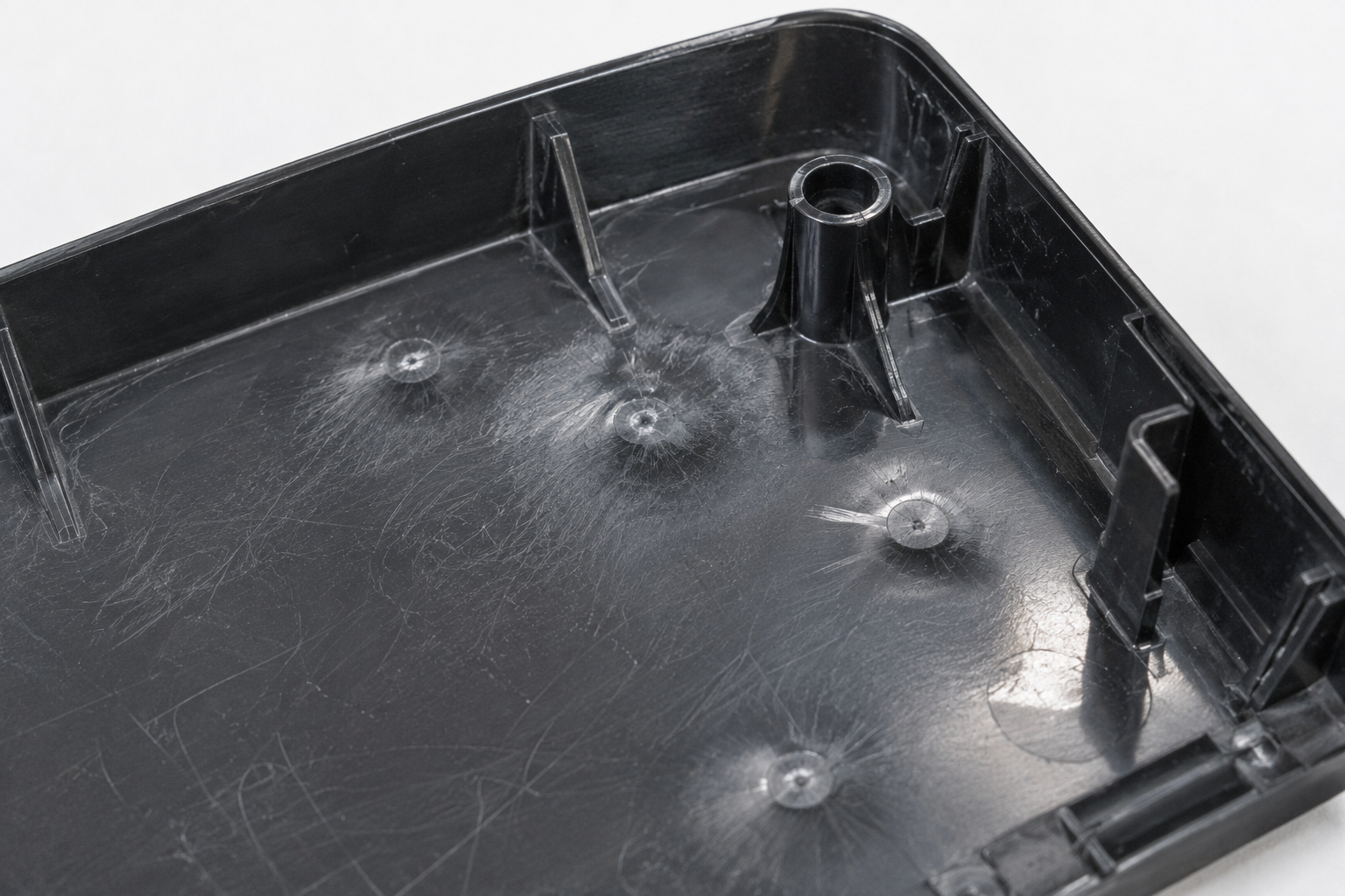
Demoulding problems

Also called: ejector marks · stress whitening · sticking

Demoulding damage - ejector marks and stress whitening
Suggested shot Ejector pin impressions raised on a surface, plus a whitened (stress-whitened) area around a pin. A sprue stuck in the cavity plate makes a good second frame.

What you see

The part is deformed by ejection forces that are too high or badly directed. Ejectors leave distinct marks - indentations, raised bosses, gloss differences or whitish discolouration (stress whitening). In the worst cases the pins puncture the part, or it cracks outright. A sprue that stays in the cavity plate belongs to the same family of problems.

Why it happens

  • Undercuts or scratches on the part and/or gating system
  • Too few ejector pins, badly positioned, or with too little contact area
  • Draft angles too small, or the surface texture depth not matched to the draft
  • Cavity overpacked during filling because holding pressure is too high
  • Excessive shrinkage gripping the core
  • Cooling time too short - the part is still soft when the ejectors move
  • Actual mould temperature too low
  • A vacuum forming between the part and the cavity surface as the mould opens
Process settings
  • Switch over to holding pressure at about 98 % volumetric fill
  • If overpacked: reduce holding pressure, or set a decreasing pressure profile
  • If shrinking onto the core: raise holding pressure and use a profile
  • Prolong the cooling time
  • Increase mould temperature
Mould & part design
  • Blend out any undercuts
  • Improve mould surface quality - polish in the demoulding direction
  • Optimise the ejector layout; increase pin diameters to spread the load
  • Increase the draft angle
  • Vent the mould inserts - channels, parting lines or special inserts - so air can flow behind the part as the mould opens and break the vacuum
Material & machine
  • Verify the actual mould surface temperature rather than the controller setpoint
  • Match texture depth to the available draft - deep textures need considerably more draft than a polished wall
Primary levers Cooling time Holding pressure Mould temp Draft angle Ejector layout
07
Surface & appearance

Jetting

Also called: worm marks · snake flow

Jetting - snake-like flow mark running from the gate
Suggested shot The characteristic snake trail running away from a pin gate. A diagram of favourable versus unfavourable gate transition radii is a valuable companion.

What you see

A snake-like, often rough or matt strand of material running from the gate across the surface. When melt passes from a small gate into a much larger cavity at high velocity with nothing to impinge on, it squirts in as a free jet, folds on itself and touches the wall intermittently. The surface of that strand has already cooled, so it never properly bonds to the melt that arrives behind it - which costs both appearance and local strength.

Why it happens

  • Gate positioned so the emerging melt meets no obstacle
  • Unsuitable gate design or too small a gate cross section
  • Unfavourable filling conditions - velocity through the gate too high
  • Part design unsuited - an abrupt wall-thickness change just past the gate
Process settings
  • Reduce injection speed - the quickest test of whether you are looking at jetting
  • Increase melt temperature
Mould & part design
  • Reposition the gate so the melt strikes an obstacle immediately - a wall or pin just beyond the gate breaks the jet and forces a proper flow front
  • Enlarge the gate cross section
  • Round off the transition between gate and part with generous radii
  • Deflect the melt by injecting through the parting surface
  • Remove abrupt wall-thickness changes along the flow path
Material & machine
  • Consider a slow-then-fast injection profile: slow through the gate to establish a front, then accelerate
Primary levers Injection speed Melt temp Gate cross section Gate position
08
Surface & appearance

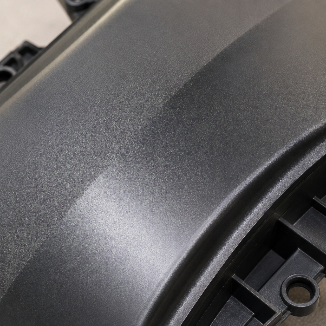
Gloss variations

Also called: gloss bands · uneven finish

Gloss variation across a moulded surface
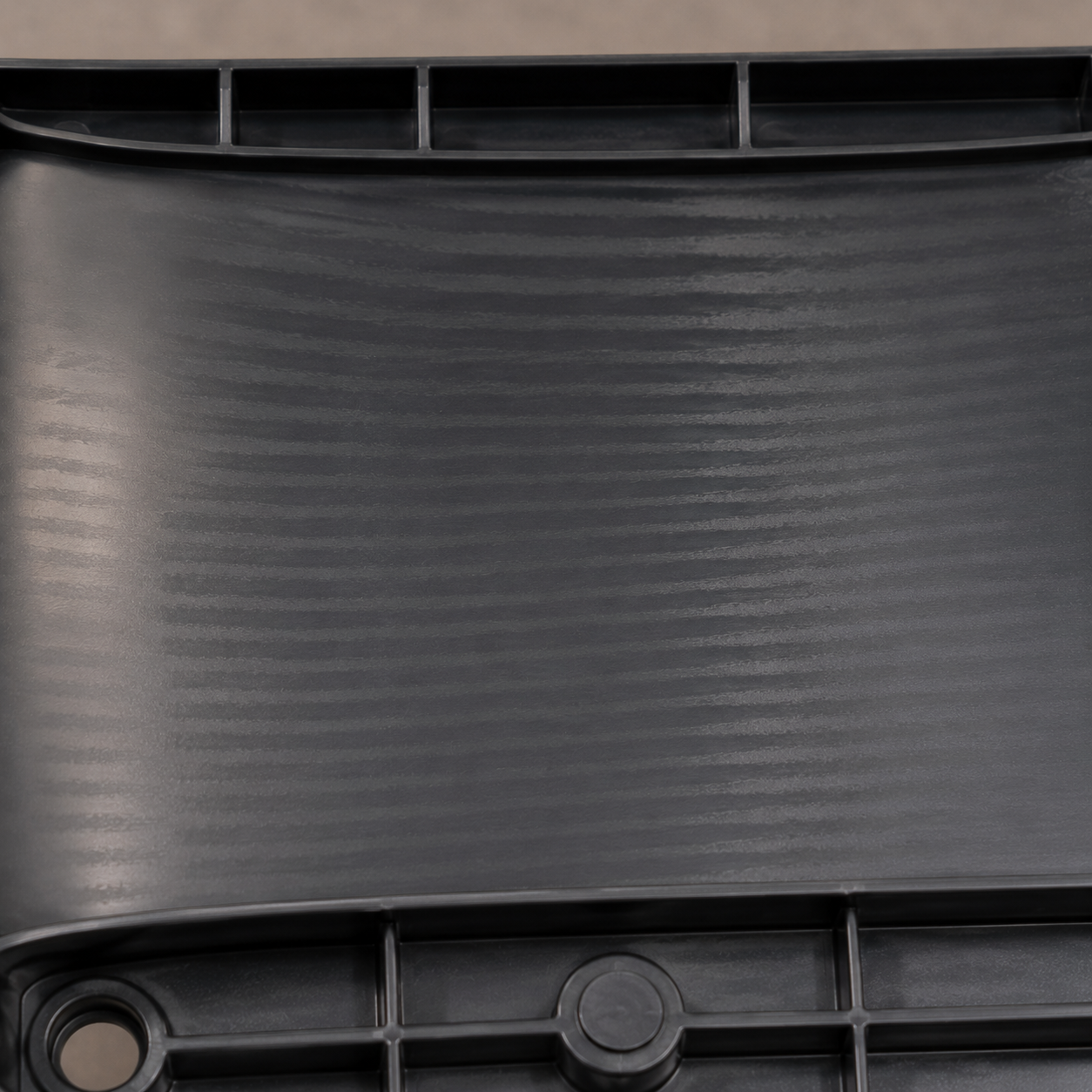
Suggested shot Two otherwise identical parts moulded at different mould temperatures, side by side under the same lighting - the single clearest demonstration that gloss is a temperature effect.

What you see

Different levels of gloss across a surface that was machined to a single finish. Gloss is simply how faithfully the frozen skin replicates the cavity. A polished tool reflects light directionally and reads glossy when replication is good; a textured tool scatters light and reads matt when replication is good. Anything that changes how the skin forms, or how hard it is pressed against the wall, shows up as a band of different gloss.

Why it happens

  • Sudden wall-thickness changes at ribs or bosses - the resulting sink marks read as gloss differences
  • Changed melt orientation and flow conditions in the area of weld lines
  • Mould wall temperature, melt temperature, injection speed or switchover point poorly chosen
  • Holding pressure level and holding time inadequate
  • Insufficient melt homogeneity
Process settings
  • Increase mould temperature - normally the strongest single lever on gloss
  • Increase melt temperature
  • Optimise injection speed
  • Switch over to holding pressure at about 98 % volumetric fill
  • Increase holding pressure, and maintain it until the gate has frozen - find the correct time by weighing parts until the weight stops rising
  • Raise back pressure and/or screw speed to homogenise the melt
Mould & part design
  • Prevent material accumulations and sudden thickness changes; gate into the thickest area
  • Move weld lines somewhere they do not matter using gate position, flow leaders or flow deflectors - a filling simulation is the efficient way to plan this
Material & machine
  • Fit a screw with a mixing section for better melt uniformity
  • Use a shallow-flighted screw
  • Install an injection unit with a larger screw diameter
Primary levers Mould temp Melt temp Holding pressure Holding time Back pressure
09
Filling & venting

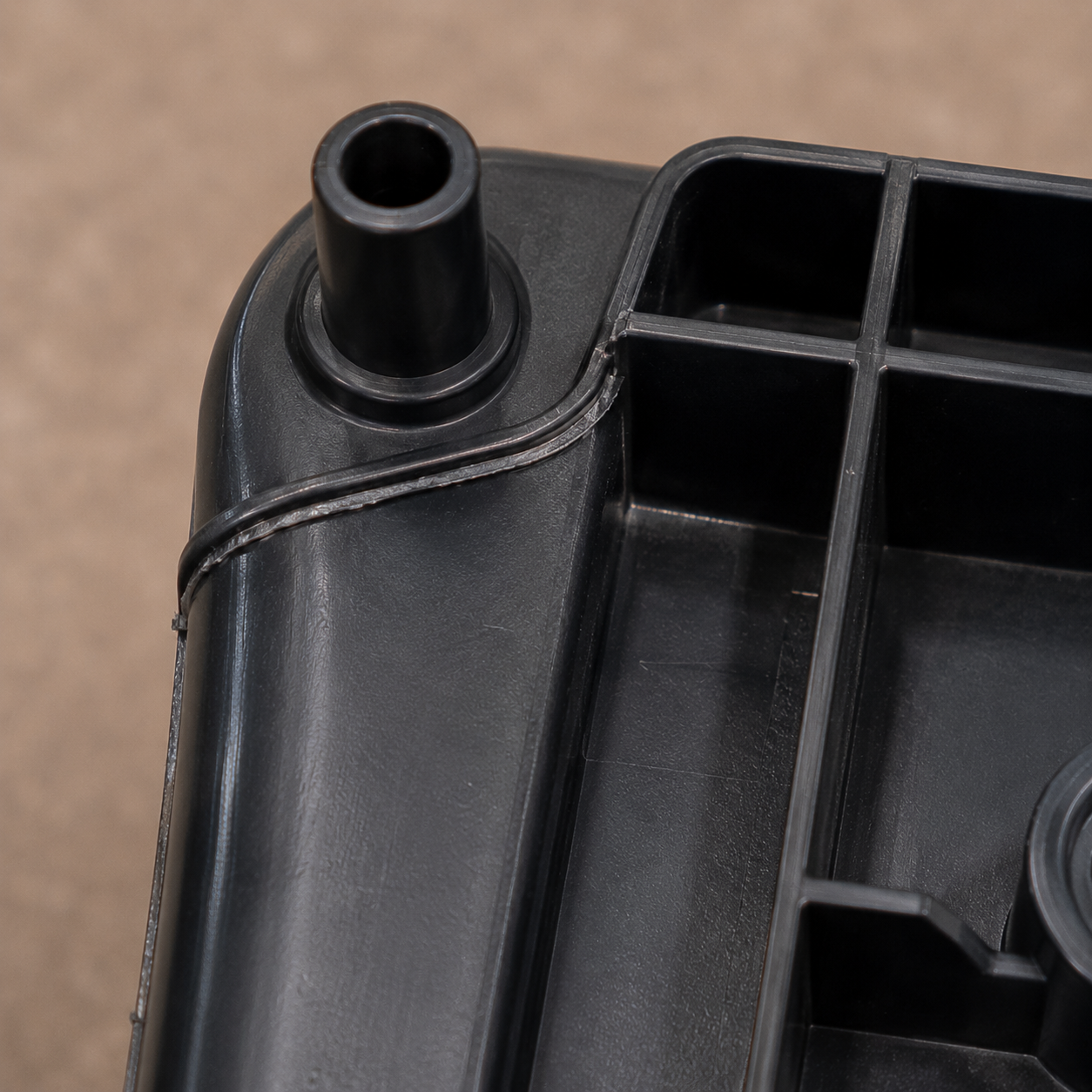
Flash

Also called: burr · spew · flashing

Flash - excess material projecting from the mould parting line
Suggested shot A thin fin of material standing along the parting line, ideally back-lit so the web of flash reads clearly against the part edge.

What you see

A fine excess of material projecting from the part where the melt has forced its way into gaps in the mould's parting surfaces, slides or ejector clearances. Flash is a pressure-versus-clamp balance problem: either the cavity pressure is higher than it should be, the melt is thinner than it should be, or the tool is not holding shut. Work out which of the three before reaching for the clamp tonnage.

Why it happens

  • Clamping force set too low, or the machine is simply undersized for the projected area
  • Fit tolerance between the mould halves, or of slides in the mould, too great
  • Sealing surfaces in the parting line damaged
  • Cavity pressure too high during the filling and holding phases
  • Melt viscosity too low - melt temperature too high, or degradation from excessive residence time or wet material
  • Mould deflecting under filling pressure
Process settings
  • Increase clamping force
  • Adjust the switchover position to occur earlier
  • Reduce injection speed, especially at the end of the filling phase
  • Lower melt temperature
  • Reduce melt residence time in the plasticising unit and hot runner
Mould & part design
  • Adjust the fit tolerances of the mould parts involved
  • Repair damage in the parting surface
  • Strengthen the mould construction if it is deflecting under pressure
Material & machine
  • Dry the material - wet hygroscopic resin degrades in the barrel, viscosity collapses and the tool flashes at a tonnage that was previously fine
  • Move to a machine with greater clamping force if the projected area genuinely demands it
Primary levers Clamp force Melt temp Injection speed Cavity pressure Drying
10
Surface & appearance

Cold slug

Also called: cold plug · comet tail

Cold slug mark near the gate of a moulded part
Suggested shot A comet-tail mark trailing from the gate on a transparent or thin-walled part. A sectioned runner showing a cold-slug well is a useful explanatory second image.

What you see

Material that solidified in the machine nozzle or hot runner before the mould filled, then got injected with the following shot. On thin-walled or transparent parts it reads as a comet-tail marking near the gate or as locally concentrated streaks. A slug that does not re-melt can obstruct the flow channel enough to split the melt and create a weld line, and in extreme cases it blocks the gate entirely and leaves the cavity short. Because it never fuses properly with the surrounding melt, local mechanical properties suffer too.

Why it happens

  • Machine nozzle temperature too low; nozzle unheated or heater-band output insufficient
  • Material drooling from the nozzle or hot runner, cooling, then being injected on the next shot
  • The nozzle bore has no draft, so the frozen skin is dragged in rather than held
  • The tip of a tunnel gate breaks off during ejection and stays in the cavity for the next shot
Process settings
  • If the nozzle is freezing: increase nozzle temperature
  • If the nozzle is drooling: lower nozzle temperature instead, and decompress by retracting the screw a few millimetres after plasticising
  • Reduce back pressure
Mould & part design
  • Incorporate a cold-slug well (catcher) in the sprue or runner - the standard, permanent fix
  • Adjust the gate angle to suit the material
  • Avoid tunnel gates on brittle grades, where the tip snaps off routinely
Material & machine
  • Add heater bands to the nozzle, or raise their output
  • Fit a needle shut-off nozzle on the machine or hot-runner nozzle
  • Modify the nozzle bore with a reverse draft so any skin is retained rather than carried forward
Primary levers Nozzle temp Back pressure Decompression Cold-slug well
11
Filling & venting

Air entrapment

Also called: gas bubbles · trapped air

Air entrapment - trapped-air bubbles in a moulded part
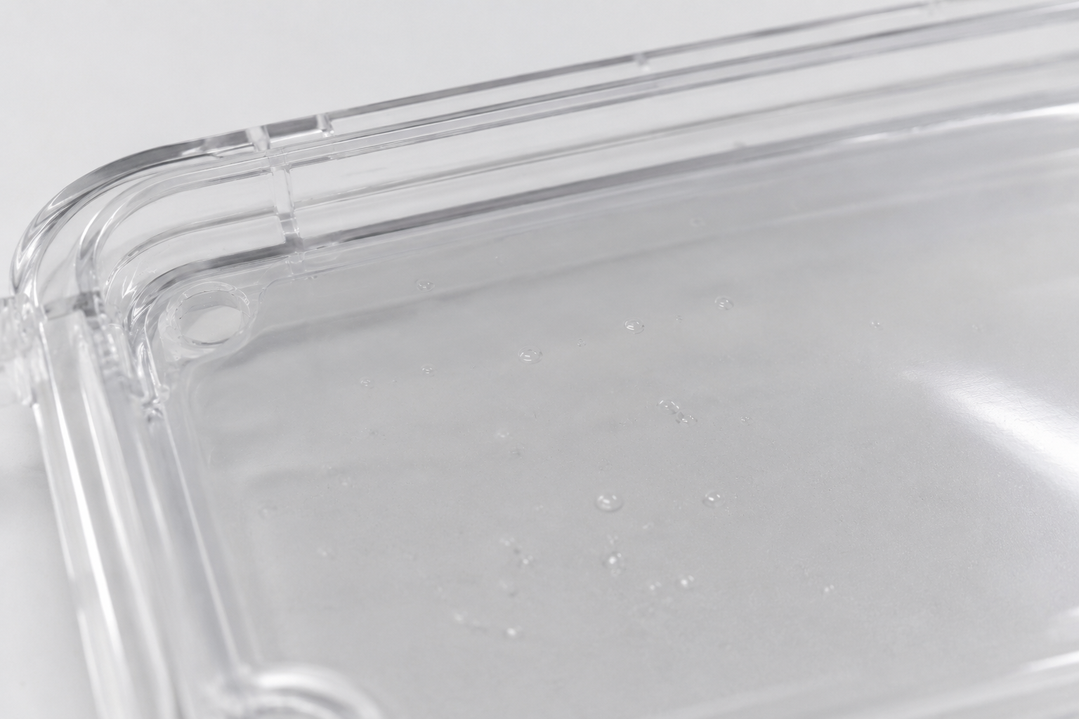
Suggested shot Bubbles visible through a transparent or natural wall, arranged along the flow direction. A CT or sectioned view showing bubbles near the outer wall separates this cleanly from voids.

What you see

The appearance depends entirely on the mechanism. If the melt flows around a pocket of air, you get anything from a short shot to surface blemishes to full dieseling. If air is folded into the melt, you get bubbles - fine to coarse, often revealing the flow direction. The diagnostic that separates this from voids: entrapped-air bubbles can sit close to the outer wall, whereas voids only ever form in the molten core.

Why it happens

  • Part design and gating create a filling pattern that surrounds and seals off air
  • Screw decompression too long or too fast after plasticising, drawing air in ahead of the screw or into the hot runner
  • Air drawn in through the feed section during plasticising - unsuitable settings or the wrong screw for the material
Process settings
  • Shorten the screw decompression stroke
  • Decompress at a reduced screw retraction speed
  • Increase back pressure during metering
  • Lower the temperature in the feed zone
Mould & part design
  • Change the filling pattern by adding flow leaders and/or flow deflectors
  • Change the position of the gates
  • In both cases, optimise the filling pattern with a flow simulation before cutting steel
Material & machine
  • Check the maximum permissible metering stroke has not been exceeded - use a larger screw diameter if it has
  • Use an optimised screw - a shallow-flighted three-zone screw, or one with a shorter feed zone
Primary levers Back pressure Decompression Feed-zone temp Gate position
12
Shrinkage & dimensional

Voids

Also called: vacuum bubbles · internal cavities

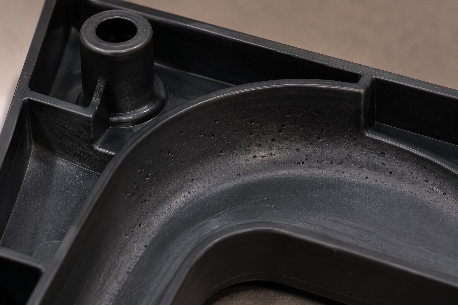
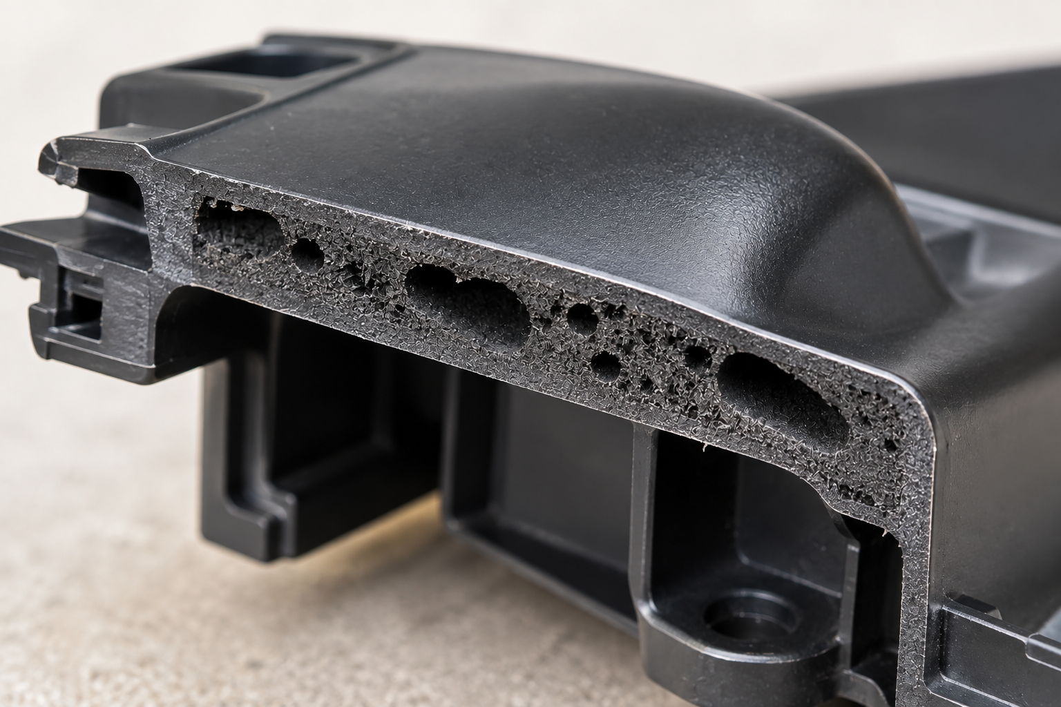
Voids - internal cavities in the wall of a moulded part
Suggested shot A polished cross-section under vertical illumination showing a void at mid-wall in a thick section - with a scale bar, since the mid-wall position is the whole diagnosis.

What you see

Hollow spaces - microcells or bubbles - formed inside the wall during or after cooling. Voids always sit in the molten core, normally mid-wall and in thick sections, which is what distinguishes them from gas bubbles. A quick field test: drill into the part while holding it under water. Water drawn in indicates a void under vacuum; bubbles escaping indicate gas. Voids share their root cause with sink marks - a void forms instead of a sink mark when the skin has already frozen hard enough to resist the contraction pulling on it from inside.

Why it happens

  • Volume contraction during cooling not sufficiently compensated by holding pressure
  • Part design unsuited - material accumulations, sudden wall-thickness changes along the flow path
  • No melt cushion
  • Large pressure loss in the machine nozzle and/or gating system
  • Part gated into a thin wall
Process settings
  • Raise holding pressure
  • Prolong holding pressure time beyond the gate freeze time - determine that time from part weight or cavity pressure, then set slightly longer
  • Reduce melt temperature
  • Increase mould temperature - then re-optimise holding time, because the gate seal point will have moved
  • Lengthen the metering stroke and adjust the switchover point
Mould & part design
  • Avoid thickness steps and material accumulations; rib thickness about half the nominal wall, without oversized radii
  • Even out wall thickness so pressure transfers properly along each flow path
  • Enlarge runner and gate cross sections - use round runners where possible
  • Gate into the thickest section
Material & machine
  • Check the non-return valve seals correctly; replace if not
  • Check the barrel for wear
Primary levers Holding pressure Holding time Melt temp Mould temp Gate cross section
13
Surface & appearance

Dull spots

Also called: gate blush · halo · gate haze

Dull spots - matt halo around the gate
Suggested shot The matt halo ringing a gate on a glossy part. A second frame showing dullness starting just after a cross-section change explains the other mechanism.

What you see

Halo-like matt patches, most often forming a ring around the gate, sometimes appearing just downstream of a cross-section change. Two things cause it: high local shear stress at these points, and reduced adhesion of the melt to the cavity wall as it negotiates the transition. Both leave the skin unable to replicate the tool finish.

Why it happens

  • Injection speed too high
  • Gate not optimally configured - too small, or with sharp transitions
  • Melt temperature too low
  • An abrupt cross-section transition in the part
  • Part gated at an unsuitable place
Process settings
  • Optimise injection speed with a graduated slow → fast profile - slow through the gate, then accelerate once the front is established
  • Increase melt temperature
Mould & part design
  • Round the gate and give it an adequate cross section
  • Design a gradual cross-section transition into the part
  • Move the gate to a less critical area, or gate through a separate runner outside the visible surface
Material & machine
  • Shear-sensitive grades and pigmented compounds show this earlier - where the finish is critical, discuss a lower-shear grade
Primary levers Injection profile Melt temp Gate cross section Gate position
14
Surface & appearance

Record grooves effect

Also called: ripples · wave marks · corduroy

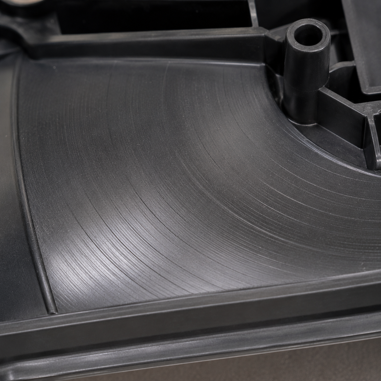
Record grooves effect - fluted marks across the flow direction
Suggested shot Concentric flutes radiating from the gate under raking light. A frame taken at the far end of the flow path shows the high-viscosity variant of the same fault.

What you see

Markings running perpendicular to the flow direction, forming a concentric or parallel fluted structure like the grooves of a vinyl record. The convex melt front cools too much at a reduced flow rate - possibly only intermittently. The frozen skin thickens until it reaches parts of the front that have not yet touched the wall, and those regions can no longer be pressed flat against the cavity even as filling continues and pressure rises.

Why it happens

  • Mould temperature, melt temperature and injection speed all set too low
  • Part design unsuited - thicker walls at the end of the flow path, or a sudden wall-thickness change
  • Large pressure loss in the gating system starving the front of pressure
Process settings
  • Increase the mould surface temperature
  • Select a higher injection speed
  • Increase melt temperature
Mould & part design
  • Optimise part geometry and remove sudden changes in wall thickness
  • Increase gate diameters to cut pressure loss
Material & machine
  • Where the effect appears only at the end of a long flow path, melt viscosity is the limit - consider an easier-flowing grade
Primary levers Mould temp Injection speed Melt temp Gate diameter
15
Surface & appearance

Coloured streaks

Also called: colour streaking · pigment streaks · marbling

Coloured streaks from uneven pigment distribution
Suggested shot Streaky, marbled colour across a moulded plaque. The most instructive pairing is the same colour run with and without a mixing element fitted to the screw.

What you see

Differences in colour across the surface - sometimes over a large area, near the gate or well away from it, frequently at weld lines and occasionally behind sharp edges. The pigment, whether from a compounded colour or a masterbatch, is unevenly distributed and has formed agglomerates. Note that the fix depends on whether you are colouring at the press or running pre-coloured compound - the two cases pull back pressure in opposite directions, so identify which you have before adjusting.

Why it happens

  • Self-colouring: unfavourable processing conditions selected
  • Self-colouring: plasticising unit unsuitable - inadequate dispersive action
  • Pre-coloured compound: pigments damaged by excessive thermal and/or mechanical load during plasticising or filling
  • Pre-coloured compound: foreign material accumulating in dead spots in the plasticising unit or hot runner
Process settings
  • Self-colouring - raise back pressure to improve dispersion
  • Self-colouring - lower screw speed; increase melt temperature
  • Pre-coloured - reduce back pressure and screw speed to stop damaging the pigment
  • Pre-coloured - check melt temperature and lower if necessary; select a lower injection speed
Mould & part design
  • Clean the plasticising unit and hot runner thoroughly
  • Eliminate dead spots where old colour can lodge and bleed into later shots
Material & machine
  • Use a plasticising unit with a longer screw
  • Install a mixing section - a mixing ring works well for self-colouring
  • Use a shallow-flighted screw instead of a standard screw: gentler melting with greater melt homogeneity
  • Confirm the masterbatch carrier and let-down ratio suit the base polymer
Primary levers Back pressure Screw speed Melt temp Screw / mixing section
16
Surface & appearance

Moisture streaks

Also called: silver streaks · splay · water streaks

Moisture streaks - silver splay marks on a moulded surface
Suggested shot Parabolic silver streaks fanning downstream, with a companion image of two purge patties - one from dried granules, one from wet - the wet one visibly foamed.

What you see

Elongated, parabolic streaks on the surface whose points always face in the direction of flow. Water in the granules flashes to steam in the barrel; the vapour bubbles burst at the advancing flow front and are smeared along the skin. There is a quick confirmatory test - purge melt into the air: if moisture is the cause, the melt foams and shows bubbles. This matters because thermal (shear) silver streaking looks similar but needs the opposite corrections - see fault 18.

Why it happens

  • Residual moisture in the granules above the limit for the grade
  • A water-cooled mould leaking into the cavity
  • Feed-hopper temperature control set too low, so condensation forms on the granules
Process settings
  • Increase the cylinder temperature below the feed hopper to prevent condensation
Mould & part design
  • Repair all leaks in the mould cooling circuit
  • As a temporary measure, run the mould heater circuit under negative pressure so any leak draws air in rather than pushing water into the cavity
Material & machine
  • Measure the actual moisture content of the granules and dry below the limit stated for the grade - do not assume the dryer is working
  • Verify the dryer is functioning: check dew point, air flow and hopper residence time
  • Hygroscopic polymers (PA, PBT, PC, PMMA, PPE) re-absorb moisture quickly once open to the atmosphere - keep them closed until use
Primary levers Drying Feed-throat temp Mould circuit integrity
17
Surface & appearance

Streaks with reinforcements

Also called: glass-fibre streaks · fibre float · fibre read-through

Glass-fibre streaks on a reinforced moulded part
Suggested shot A glass-filled plaque with visible surface fibre, shot at a low angle. A pair moulded at low and high mould temperature demonstrates the primary fix.

What you see

In glass-fibre reinforced or mineral-filled grades: rough, spotty, irregular surface areas, or uniform blemishes whose shape partly follows the flow front in that region. Depending on how the light falls they read anywhere from matt to metallically glossy. They appear mainly after openings, diversions and at weld lines - wherever the resin-rich skin that normally covers the fibres fails to form.

Why it happens

  • Injection speed too low
  • Mould surface temperature too low - the skin freezes before resin can cover the fibre
  • Melt temperature not high enough
  • Fibre orientation changing at material accumulations - thickness steps, ribs and mounting bosses
Process settings
  • Increase injection speed - a graduated profile is often practical
  • Increase mould temperature - usually the most effective single change
  • Increase melt temperature, including in the hot runner
Mould & part design
  • Check whether material accumulations and sudden wall-thickness changes can be designed out
Material & machine
  • Where appearance is critical, move to a surface-improved reinforced grade - these are formulated specifically to keep fibre off the skin, and the difference is dramatic
  • Talk to us about grade options before accepting a cosmetic compromise on a reinforced part
Primary levers Mould temp Injection speed Melt temp Grade selection
18
Surface & appearance

Burning streaks

Also called: brown streaks · thermal silver streaking · degradation streaks

Burning streaks from thermal degradation of the melt
Suggested shot Two parts moulded 20 °C apart in melt temperature, showing brown streaking appear on the hotter one. A separate frame of silver streaking radiating from a restrictive gate covers the shear mechanism.

What you see

Charred streaks in silver, light-brown or very dark shades. Severe thermal damage to the melt generates gas bubbles that reach the surface during injection. The colour tells you which mechanism you have: light-brown to very dark discolouration indicates real thermal damage from oxidation or degradation - too hot, or too long in the barrel. Silver streaks normally result from excessive friction, usually localised at a small flow-channel cross section or a sudden diversion around an obstacle.

Why it happens

  • Melt damaged by an excessively high temperature
  • Melt damaged by an excessively long residence time
  • High shear during the mould filling procedure
Process settings
  • Measure the actual melt temperature with a needle pyrometer and confirm it sits inside the permissible window - then lower barrel and hot-runner temperatures if it does not
  • Reduce screw speed and/or back pressure
  • Optimise the injection speed and profile
  • Check whether the machine has been standing - degraded melt from a stoppage looks identical
Mould & part design
  • Check and enlarge the flow cross sections of the gate, sprue and hot-runner system - the usual source of shear-induced silver streaking
  • Reduce hot-runner residence time via a shorter cycle or smaller channel diameters
Material & machine
  • Check barrel residence time - change to a smaller barrel or a shallow-flighted screw if the shot size is a small fraction of barrel capacity
  • If the streaking is silver rather than brown, rule out moisture first (fault 16) before chasing temperature
Primary levers Melt temp Residence time Screw speed Back pressure Gate cross section
19
Surface & appearance

Tiger lines

Also called: tiger stripes · flow marks · chatter

Tiger lines - alternating matt and glossy bands
Suggested shot Alternating matt and glossy bands across a long flow path. A before/after pair with a larger gate fitted shows the fix better than anything else.

What you see

Alternating glossy and matt stripes running perpendicular to the flow direction, resembling the coat of a tiger. They are caused by a pulsating, unstable melt flow - the front alternately sticks and slips at the wall. This is characteristic of multi-phase systems and blends, where the phases behave differently at the melt front. Almost always a pressure-loss problem in disguise.

Why it happens

  • Gate, sprue and runner cross sections too small
  • Machine nozzle bore too small
  • Part wall thickness insufficient
  • Large pressure loss along the flow path
  • Tool temperature too cold
Process settings
  • Increase melt temperature
  • Increase tool temperature to the maximum recommended for the grade
Mould & part design
  • Increase the cross sections of the gating system and runners - the primary fix
  • Check whether the wall thickness of the part can be increased
Material & machine
  • Install a machine nozzle with a larger bore diameter
  • Blends and impact-modified compounds are inherently more prone to this - grade choice matters where a long, thin flow path is unavoidable
Primary levers Gate / runner size Mould temp Melt temp Nozzle bore
20
Demoulding & stress

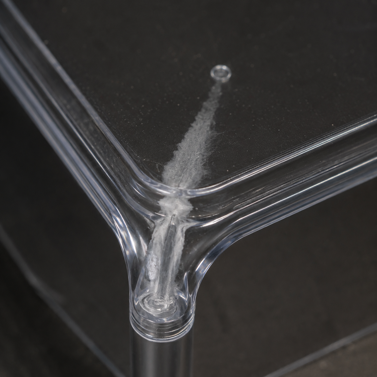
Stress crack formation

Also called: ESC · environmental stress cracking · crazing

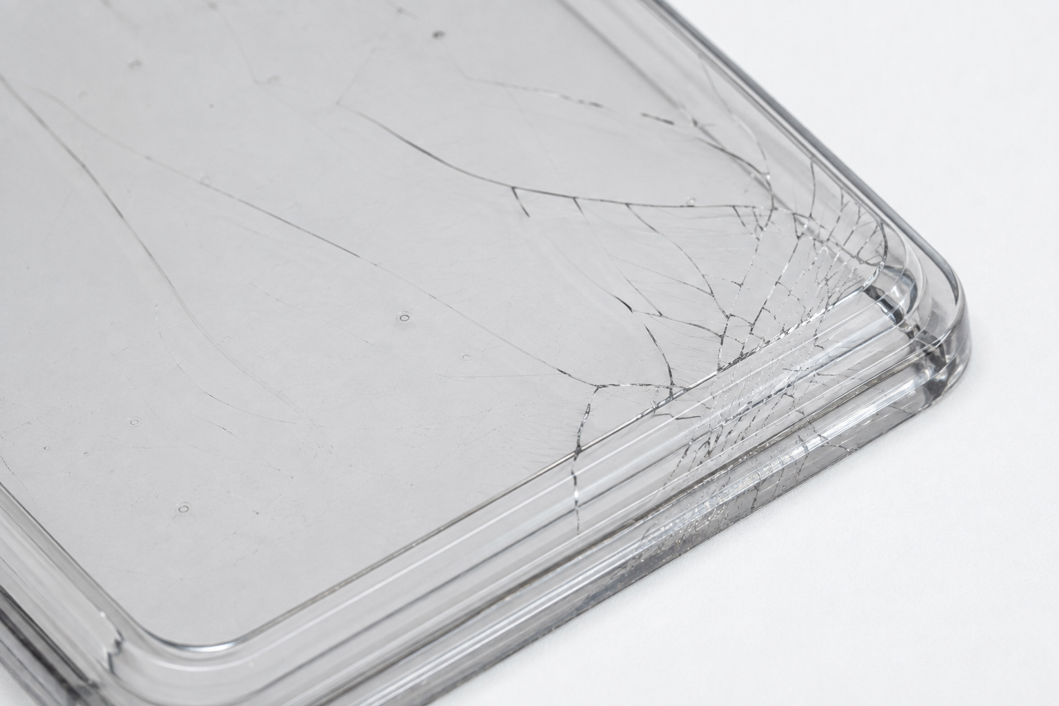
Stress cracking in a moulded part
Suggested shot A part after solvent exposure showing a crack network concentrated at the highest-stress region. A series moulded across a range of mould temperatures makes the point that frozen-in stress is a process variable.

What you see

External or internal cracks appearing at stresses well below the material's ultimate tensile strength. Locked-in internal stress from processing is a major contributor; the crack itself is then initiated by an external tensile load and/or contact with an aggressive solvent or chemical. Because the process-induced portion is the part you can control, deliberate solvent exposure is a standard way to reveal how much stress a moulding is carrying. Mould temperature is usually the dominant variable.

Why it happens

  • Material overloaded because holding pressure is too high, or the mould construction is inadequate
  • Mould temperature too low - the melt freezes under stress rather than relaxing
  • Cracks formed during ejection by forced removal from undercuts - insufficient draft, too few or badly positioned ejectors
  • Molecular weight of the chosen grade too low for the chemical environment it will meet in service
Process settings
  • Increase mould temperature - allows stress to relax before the part freezes, and normally the single most effective change
  • Reduce back pressure; consider a decreasing back-pressure profile
  • Review holding pressure - overpacking locks stress into the part
Mould & part design
  • Improve the mould construction
  • Reduce the undercut, or design it out
  • Ease demoulding with larger draft angles
  • Optimise the ejector system so load is spread rather than concentrated
Material & machine
  • Use a grade with higher molecular weight - essential when aggressive solvents or chemicals are part of the service environment
  • Where the part meets chemicals in service, treat chemical compatibility as a selection criterion, not an afterthought - talk to us before qualifying the grade
Primary levers Mould temp Back pressure Holding pressure Draft angle Grade selection
21
Material & contamination

Unmolten material

Also called: unmelts · unmelted granules · cold pellets

Unmolten material - unmelted granules in a moulded part
Suggested shot Raised lens-shaped contours on a thin wall, and - for a natural unreinforced grade - a transmitted-light frame showing the more transparent inclusions.

What you see

In semi-crystalline thermoplastics, granules that have not fully melted pass through the screw and end up in the part. On thin walls they raise a visible contour or elevation on the surface. In unreinforced, uncoloured grades they appear as inclusions of greater transparency than the surrounding material. This is a plasticising problem, not a mould problem - nothing you do to the tool will fix it.

Why it happens

  • Unfavourable plasticising conditions selected
  • Residence time of the material in the cylinder too short
  • Screw geometry unsuited to the material
Process settings
  • Select a flat (horizontal) barrel temperature profile instead of a rising one - this gets heat into the granules earlier
  • Increase melt temperature
  • Raise back pressure to add shear heating and improve melting
Mould & part design
  • No mould-side remedy - this fault originates entirely in the plasticising unit
Material & machine
  • Pre-heat the granules
  • Use a machine with a larger screw diameter, or a longer injection cylinder
  • Fit a screw designed for the material - shallow-flighted three-zone screws give good results
  • Check the metering stroke is not excessive for the barrel
Primary levers Melt temp Back pressure Barrel profile Screw geometry
22
Filling & venting

Short shot

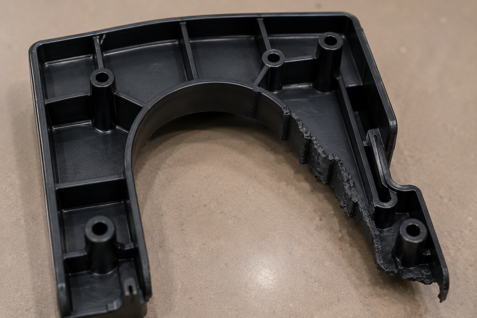
Also called: incomplete fill · non-fill · short mould

Short shot - incompletely filled moulded part
Suggested shot A short-shot study - a series of parts at increasing shot volume showing the cavity filling progressively. This doubles as the single most useful process-setup image on the whole page.

What you see

The part is not completely formed - most often in the areas furthest from the gate or in the thinnest sections, because the cavity never fully filled. Worth noting: a short shot is not always a volume problem. Trapped air with nowhere to go will stop a flow front just as effectively as insufficient material, so check venting before you simply add shot weight.

Why it happens

  • Not enough melt metered; no melt cushion
  • Melt temperature and/or mould temperature too low
  • Injection speed too low
  • Mould not adequately vented - trapped air blocks the front
  • Too much pressure loss in the gating system
  • Wall designed too thin, or the flow path too long for the grade
  • A thin-walled area near the gate freezing off during filling
  • Flowability of the grade insufficient even after process optimisation
Process settings
  • Increase the metering stroke and confirm a cushion remains
  • Increase melt temperature first - it lowers filling pressure directly. Only then raise mould temperature, which also lengthens the cooling time
  • Increase injection speed
Mould & part design
  • Check the vents and improve cavity venting
  • Enlarge the flow cross sections of the nozzle, runners and gates
  • Change gate position or increase the number of gates; add a runner
  • Introduce a flow leader where possible
  • Re-gate so that the thin-walled area fills last
  • Increase the wall thickness of the part
Material & machine
  • Check the function of the non-return valve - a worn valve loses shot volume and cushion, and mimics every other cause on this list
  • Use a material that flows more easily - where the flow-length-to-wall-thickness ratio is genuinely at the limit, a higher-flow grade is the correct answer rather than more pressure
Primary levers Shot volume Melt temp Injection speed Mould temp Venting
23
Shrinkage & dimensional

Warpage

Also called: distortion · twist · out-of-flat

Warpage - distortion of a moulded part
Suggested shot A flat part on a surface plate with a visible gap at one corner. Alongside it, a simulation image of fibre orientation before and after geometry optimisation shows why reinforced parts warp.

What you see

The part deviates from its intended shape - twisting, bowing, wavy surfaces, angles out of tolerance. The driver is always differential shrinkage: different regions shrink by different amounts because they were packed differently or because molecular and fibre orientation varies from place to place. In glass-fibre reinforced grades this is dominated by fibre orientation, which is why shrinkage along the flow differs from shrinkage across it - and why warpage in reinforced parts is largely designed in, not dialled out.

Why it happens

  • Unfavourable mould temperatures, or an unfavourable difference between the two halves
  • Part has differing wall thicknesses
  • Pressure gradient along the flow path too high
  • Cooling time too short - the part is ejected too hot and deforms afterwards
  • Unfavourable material choice for a warp-critical geometry
  • Fibre orientation changing across the part - from flow diversions, end-of-flow effects, weld lines and gates
Process settings
  • Set different temperatures for the two mould halves and for sliding cores. Effective mainly on unreinforced thermoplastics - BASF's published example shows a part going from −1.4 to +2.6 to +0.4 as the core side ran at 80 °C, 30 °C and 50 °C against a fixed 80 °C cavity
  • Select a longer cooling time
Mould & part design
  • Even out wall sections; blend out abrupt differences
  • Gate in several places - recommended for unreinforced grades only
  • Check the part is not catching on a negative draft as it ejects
  • For reinforced grades: gate to establish one uniform flow direction; gate elongated parts lengthwise; avoid ribs and walls perpendicular to flow; place the end of the flow path in corners; aim for abutting weld lines and keep them off exposed webs - weighing this against the strength loss at the weld
Material & machine
  • Use low-warpage grades - blends with an amorphous phase have a smaller difference between lengthwise and crosswise shrinkage, which is the property that causes warpage in the first place
  • Use numerical simulation to predict filling behaviour and fibre orientation before cutting steel - for a warp-critical reinforced part this is not optional
Primary levers Mould temp balance Cooling time Gate position Wall uniformity Grade selection
24
Material & contamination

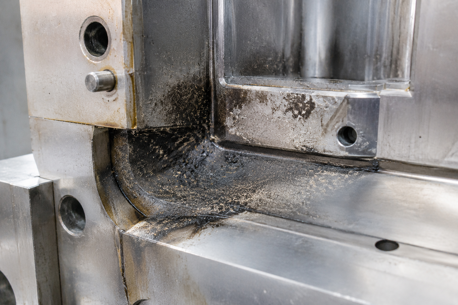
Plate-out / mould deposit

Also called: mould fouling · die deposit

Plate-out / mould deposit on the cavity surface
Suggested shot Deposit build-up on a cavity surface at the end of the flow path and around a weld line. A vent-land cross-section diagram with dimensions is the ideal companion graphic.

What you see

Deposits accumulating on the cavity surface, in the parting line and inside the venting system. The residue can be polymer breakdown products, additives or flame retardants that volatilise from the melt and condense on the cooler tool. It matters because it is self-accelerating: deposit blocks the vents, blocked vents cause dieseling and burning, and the resulting degradation generates more deposit.

Why it happens

  • Melt temperature too high
  • Injection speed too high during filling
  • Material insufficiently dried
  • Mould not adequately vented
  • Residence time too long in the plasticising unit and/or hot runner
  • Melt exposed to severe shear along the flow path
Process settings
  • Check melt temperature at the nozzle with a needle pyrometer against the recommended window - measured, not the controller reading - and lower if necessary
  • Reduce screw speed; often it is enough to slow only the end of the filling phase with a graduated profile
  • Reduce hot-runner residence time via a shorter cycle or smaller channel diameters
Mould & part design
  • Check vent position and effectiveness; add vents in the parting surface and fit core and ejector pins where melt fronts meet
  • BASF's guidance for vent land depth is roughly 0.01–0.03 mm, and for easy-flowing materials 0.01–0.02 mm to avoid flashing the vent
  • Enlarge gate, sprue and runner cross sections; fit a machine nozzle with a larger flow diameter
Material & machine
  • Measure granule moisture and dry below the grade limit
  • Check barrel residence time; switch to a smaller barrel or a shallow-flighted screw
  • Flame-retardant and highly additivated compounds plate out sooner - build vent cleaning into the maintenance schedule rather than waiting for burn marks
Primary levers Melt temp Screw speed Drying Venting Residence time

Which parameter moves which fault

Use this when you are fighting two defects at once and need to see where the fixes conflict. Raising mould temperature helps gloss, fibre streaks and stress cracking - but it lengthens the cycle and works against sink marks. The arrows show the direction each fault's remedies push a parameter, taken directly from the corrective actions listed above.

↑ Increase ↓ Reduce ↕ Change / optimise - direction depends on the specific cause · Not a primary lever
Injection moulding defects cross-referenced against process parameters
Defect Melt temp Mould temp Inj. speed Hold press. Hold time Back press. Screw speed Cooling time Cushion / metering Drying Venting Gate & runner Part design
01 · Weld line↑·↕·······↕↕↕
02 · Delamination↑·↓··↑··↕··↑↕
03 · Diesel effect··↓·······↕↕·
04 · Black specks↓····↓↓↓···↕·
05 · Sink marks↓↓·↑↑···↑··↑↕
06 · Demoulding·↑·↕···↑··↕·↕
07 · Jetting↑·↓········↕↕
08 · Gloss variations↑↑↕↑↑↑↑····↕↕
09 · Flash↓·↓↓·····↑···
10 · Cold slug↕····↓··↕··↕·
11 · Air entrapment↕····↑··↕··↕↕
12 · Voids↓↑·↑↑···↑··↑↕
13 · Dull spots↑·↕········↕↕
14 · Record grooves↑↑↑········↑↕
15 · Coloured streaks↕·↓··↕↕······
16 · Moisture streaks·········↑···
17 · Streaks with reinforcements↑↑↑·········↕
18 · Burning streaks↓·↕··↓↓↓···↑·
19 · Tiger lines↑↑·········↑↕
20 · Stress cracking·↑·↓·↓······↕
21 · Unmolten material↑····↑··↕····
22 · Short shot↑↑↑·····↑·↕↑↕
23 · Warpage·↕·····↑···↕↕
24 · Plate-out↓·↓···↓↓·↑↕↑·

Still fighting the same defect?

Some problems are not process problems. If you have worked through the settings and the fault is still there, the answer is often the grade - flow length, fibre content, molecular weight or a surface-improved variant. That conversation is what we do.

Talk to our technical team

Sources & further reading

  • BASF Plastics, Injection-Molding Problems in Engineering Thermoplastics - Causes and Solutions (publication KTE 0802 BE, August 2009). The primary technical source for the defect descriptions, causes and corrective actions on this page. Examples referenced in the text relate to BASF's Ultramid® (PA), Ultradur® (PBT), Ultraform® (POM) and Ultrason® (PSU/PESU/PPSU) product families.
  • Vital Polymers application engineering - practical notes from grade selection and trial support with manufacturers in Pakistan.

General processing guidance only. Processing windows, drying conditions and permissible melt temperatures are specific to each grade - always work to the technical data sheet for the material you are running, and never exceed its stated maximum melt temperature. Nothing here implies a guarantee of properties or of suitability for a particular purpose. All trademarks are the property of their respective owners.